The official version of this document can be found via the PDF button.
The below content has been automatically generated from the original PDF and some formatting may have been lost, therefore it should not be relied upon to extract citations or propose amendments.
PROPOSED DESIGN AND COSTS OF AN IN-VESSEL COMPOSTING FACILITY
for
States of Jersey
U124 Aberdeen House 22 Highbury Grove London
N5 2EA
U.K.
+44(0) 20 7288 8759
johnb@verno.co.uk www.verno.co.uk
The Wasteology In-vessel Composting System November 2004

INDEX
Page
- Introduction 3
- Site Design 3
- Realistic Tonnage 3
- The Vessel Design 3
- Temperature Monitoring 8
- Description of the Process and Operations 13
- Overview of the Process 13
- Daily Order of Operations 13
- Monitoring, Cleaning and Record Keeping 13
- Monitoring 13
- Cleaning 13
- Record Keeping 14
- Waste Reception/Pre-processing 14
- Active Composting Phase 16
- Barrier 1 16
- Barrier 2 16
- Transfer from Barrier 1 to Barrier 2 16
- Maturation Phase 16
- Product Preparation 17
- Hazard Analysis and Critical Control Points (HACCP) Assessment 17
- Overview of HACCP System 17
- Hazard Analysis 17
- HACCP Plan 18
- Verification Schedule 18
- Costs 18
5.1 Note on Costings 18
- Introduction
The following document given by Wasteology and Verno is to describe a five (ten) in-vessel system (30,000 tons/year) options for source separated household waste, consisting of garden waste and kitchen waste including meat. Therefore the system has to comply with the Animal By-Product Regulations 2003.
The report is split into several parts. The first part, Section 2 Site Design, details the varous aspects to the site design that are proposed or need to be considered. The second part, Section 3 Description of the Process and Operations, describes the mode of operation for the site and also other aspects that need to be considered. The third part, Section 4 Hazard Analysis and Critical Control Points (HACCP) Assessment, details the HACCP for the system.
- Site Design
- Realistic Tonnages
Each vessel has the approximate dimension of 15m x 8m x 2.5m, which gives a volume per vessel of approximately 300m[3]. If the bulk density for the waste to be used is approximately 0.6 ton/m3, then each clamp will hold approximately 175 tons of material, and gives an annual tonnage of approximately 9000 tonnes. However, taking into account variation in density of the feed a more realistic figure of 6000 tonnes per annum should be taken. This gives figures for:
3 pairs of vessels – 18,000 tonnes per annum
4 pairs of vessels – 24,000 tonnes per annum
5 pairs of vessels – 30,000 tonnes per annum
- The Vessel Design
Each vessel is 14.75 metres long by 8 metres wide and is made from concrete A-blocks. Each A- block is 2.44 metres high by 0.76 metres wide by 1.23 metres long, and is bolted to the pad using threaded bar and epoxy resin to a depth of about 150mm. They are also connected to the next A- block via interconnecting plates.
![]()
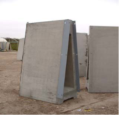 Connecting plates
Drawings of the vessel, roof and frontage showing the position of the fan and pipes as well as the position of the air ducts are available on request. On top of the row of A-block runs a channel, which not only guides the retractable roof back and fro but also acts as a gutter for rainwater falling on the roofs. As the pad is sloped towards the middle, the rain water can be collected at the front of the vessel and moved straight down plastic pipes into either a pipe under the pad and then collected or piped back through the A-blocks to the back wall and then collected. The advantage of the second method is that no pipes are laid into the concrete allowing easier access.
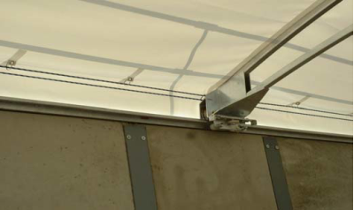
The channel also houses the safety rails. The roof are made in sections, which not only allows the roof to concertina to the back thereby enabling loading and unloading of the tunnels to be carried out safely, but also enables sections to be replaced without the need to replace the whole roof. This becomes very useful as buckets will inevitably tear small holes in the roof.
Four air ducts are laid along the length of the vessel, and consist of a bottom rail, which is bolted to the pad and the top rail which is then clipped in. The air ducts also come in, which enables the replacement of just the damaged section and not the whole length of the air duct.
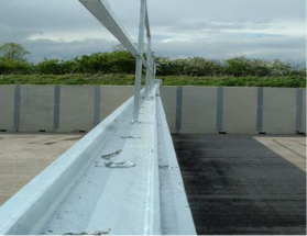
Photograph 2: Channel to guide retractable roof and rainwater
![]()
 Safety rails
![]() Channel
Channel
 Rainwater pipe
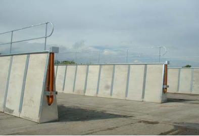
Photograph 3: A-blocks with channels, rainwater pipes and safety rails.
![]()
 Guide ropes
 Roof rails and wheels
Photograph 4: Roof rails guided by wheels and moved back and fro using ropes
Photograph 5: Roof concertinas to the back wall of the vessel

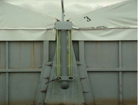 Winding Mechanism
Photograph 6: Winding mechanism
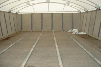
Photograph 7: Air pipes
The roof is moved back and fro using a simple pulley system based on ropes and a winding mechanism. This can be upgraded to an electrical driven system, details to follow later.
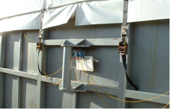
Each individual vessel has its own fan. This enables better control of the air flows through the vessel and also ensures even distribution of air through each air duct within that vessel. Each vessel fan is fixed to the back wall with the suction pipe hanging' over the top of the wall. The use of closed loop system' for aeration, that is suction from the top of the vessels under the covers and pushing it back through the air pipes into the material, not only has the advantage of blowing warm air through the material, thereby increasing the temperatures, but also using the material its self to clean any odours within the system, thereby acting similar to a bio-filter.
![]()
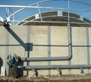 Suction pipe
![]() Fan
Fan
![]() Outlet pipe
Outlet pipe
 Connection to air pipes
Photograph 8: Fan system
The doors are taken off and replaced using an attachment, which can be fitted to a telescopic handler. The doors slide into slots attached to the A-blocks. The roof is then brought forwards and the roof flap secured to give an enclosed environment.
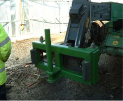
Photograph 9: Attachment for moving the doors

Photograph 10: Door in place, roof brought forwards
Photograph 11: Door being lowered into position
Photograph 12: Roof flaps secured
2.4 Temperature Monitoring
The temperature is continually monitored, logged and sent wirelessly to a receiver in the staff office. This records and stores the data and produces a live' picture of the temperature in each vessel. The probes record the temperature every 10 minutes. Further detail will follow later.
Each temperature probe will have a unique number and assigned to a specific tunnel and to a specific area within that vessel, thereby ensuring consistency in monitoring temperatures and preventing a potential route for cross contamination.
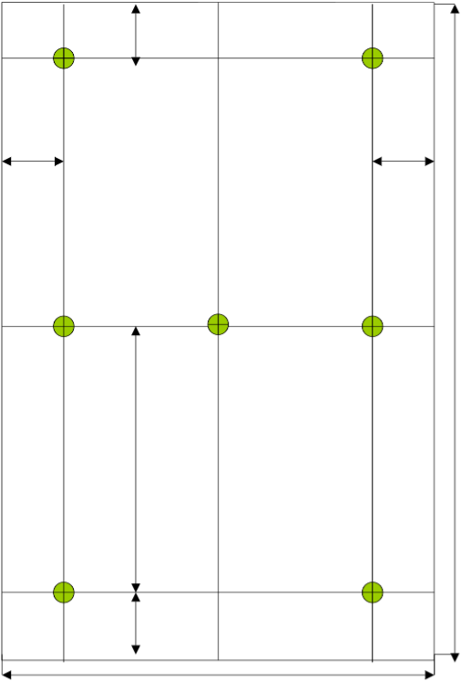
Six temperature probes are inserted into the waste at regular intervals, 2 at the front, 2 in the middle and 2 at the back, with another temperature probe being placed on the surface in the middle of the tunnel, as shown below in Diagram 2: Temperature Probe Distribution.
As required under the Animal By-Products Regulations 2003 all temperature probes need to be independently calibrated every 3 months, and this can be arranged.
Diagram 2: Temperature probe distribution (clamp top view, not to scale)
 0.5m
0.5m
A B
0.5m 0.5m
15m
B (Flat-plate A
temperature sensor
on surface of
composting material)
7m
A B
0.5m
8m
![]() A = Vertical temperature probe, tip 1.5m below surface of waste B = Vertical temperature probe, tip 1.0m below surface of waste
A = Vertical temperature probe, tip 1.5m below surface of waste B = Vertical temperature probe, tip 1.0m below surface of waste
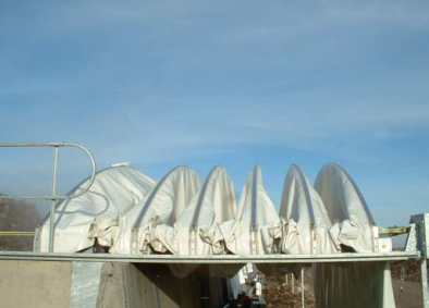
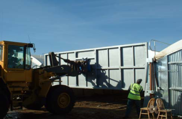
Photograph 13: Front view of four vessels
12![]()
- Description of the Process and Operation
- Overview of the Process
The composting process is divided into three clearly defined stages: material reception/pre- processing, active composting phase and maturation. The material reception/pre-processing stage involves delivery, inspection of the material and shredding of the material. In order to comply with the Animal By-products Regulations 2003 the active composting phase is divided into two composting phases known as Barrier 1 and Barrier 2, each lasting one week. Finally, the composted material from Barrier 2 is transported to the maturation area where it is matured and screened. Diagram 1 below gives an overview of the process.
- Daily Order of Operations
The Animal By-product Regulations 200, states clearly that composting facilities must have a clean end' and a dirty end', with the reception building as the dirty end and the maturation area the clean end. In order to maintain this state one option is given below. This involves moving from the clean end of the process to the dirty end in order to prevent contamination, and making sure that each stage is completed before moving onto the next. It is important to carry out the stages given below in a defined order, these are as follows:
Stage 1 – emptying of the Barrier 2 tunnel and transporting the composted material to the maturation area using a telescopic handler and a green bucket.
Stage 2 – transfer of the composted material from Barrier 1 to Barrier 2 tunnel using the same telescopic handler but with an orange bucket.
Stage 3 – filling of Barrier 1 clamp with pre-processed material, red bucket.
It should be noted that as the reception area is housed, reception and pre-processing of the material may take place at any time. It should also be carefully noted that while the flow of the material is from dirty end to clean end, the daily order in which the separate stages are carried out is from clean end to dirty end.
Using the above system means that the site can be run using two telescopic handlers. One machine is used to load the shredder and load Barrier 1 vessels, while a second machine is used to unload Barrier 2 then transfer material from Barrier 1 to Barrier 2. It is assumed that the material will be matured in piles and screened elsewhere.
- Monitoring, Cleaning and Record Keeping
In order to satisfy the State Veterinary Service and HACCP requirements monitoring of the process and site is very important as well as regular cleaning of the site and record keeping.
- Monitoring
Monitoring of the site needs to be carried out at probably twice a day by the Site Manager. His duties need to include checking for any spills, checking the integrity of the site fence and making sure that operations are being carried out accordance with the SOP, Standard Operating Procedure, and the HACCP Plan. Also he needs to be responsible for recording temperatures from Barriers 1 and 2, both manual recording as those logged continually. This data is necessary for him to decide if the material has passed its time/temperature requirements and is safe to procedure to the next stage.
- Cleaning
Cleaning routines are very important and need to be described in the HACCP for individually areas around the site. For example any spilled material which occurs outside the reception area needs to be cleaned up immediately, and the designated cleaning area for wheels needs to be kept clean and washed down at the end of the day. The water from this area then needs
to be collected and piped to the leachate tank. Similarly after the material has been transferred from Barrier 1 to Barrier 2, the telescopic handler and bucket need to be thoroughly cleaned using the wash-down facilities. Also at the end of the day the reception building, the area around the tunnels need to be cleaned using the wash down facilities.
- Record Keeping
Record keeping are very important and all work needs to be logged in the site diary along with any comments. For example all cleaning actions taken and any rejected loads should be logged in detail along with any equipment used and any appropriate action that was taken. The composting process needs to be recorded to achieve some traceability. For example records of waste delivery need to be documented along with formation of the batch, the Batch Number, the temperatures within that batch for both Barrier 1 and 2 as well as its history within the product preparation area.
- Waste Reception/Pre-processing
Kerbside collected material is emptied into the reception building where the pre-processing also takes place.
On leaving the site, the wheels of the delivery vehicles are inspected for any contaminants and cleaned in the designated area using a pressure-washer. This is to prevent debris from being deposited on the roads and thereby minimize the risk of spreading any contamination.
The material is visually inspected and any large contaminants removed and placed in a skip held within the building. The skip is periodically removed and sent to landfill. The material is further inspected to ensure it is catering waste, as defined under the ABPRs 2003. If the waste is found to contain any other type of animal by-products, it is removed to a quarantine area, and advice sought from the local Trading Standard Officers and/or local vets as to the necessary course of action.
The material is loaded into a shredder in the reception building using a telescopic loader. This reduces the particle size to an acceptable value usually about 120 mm. Leachate from the leachate tank can be added to the material at this stage using an irrigation system. This provides the required moisture to the material as well as using a waste stream that would otherwise require disposal. The waste is then ready to be loaded into the Barrier 1 vessels. The telescopic loader is identified by its red bucket and is confined to the reception building and loading of Barrier 1 in order to minimize the risk of spread of contamination.
Material is processed immediately on arrival. However, if a problem does occur the material is processed within 24 hours of receipt. If for any reason the problem ensures processing cannot be achieved within the 24 hours, the material is diverted to landfill.
The material reception/pre-processing building is be considered as the "dirty end" of the composting process. Therefore, all operatives are required to change clothing and footwear when moving between this area and other areas of the site. This is carried out in the changing rooms attached to the building. The clothing and footwear are colour-coded, red, for ease of identification.
Diagram 1: Process Flowchart showing Critical Control Points
Duration |
| Critical Control Points (Hazards) |
|
| Waste delivery |
24 hours |
|
area by delivery vehicles leaving the site)
(Processing delay)
(Cross-contamination via spills)
All operations involving movement of site operatives from dirty to clean areas |
| ||
1 weeks |
| (Cross contamination via clothing and footwear) 5 Transport of compost and digesting residues from Barrier 2 to maturation area |
| ||
1 weeks |
| (Cross-contamination via vehicles and containers) 6 Transport of compost and digesting residues from Barrier 1 to Barrier 2 (Cross-contamination via vehicles and containers)
Pre-processing phase (Access of birds or vermin to waste) Active composting phase (Access of birds or vermin to waste) Screening before Barrier 1 |
8 weeks | ||
| ||
|
|
|
1 day |
|
11 phase/Barriers 1 & 2 (Time/temperature requirements are not met) Sampling after Barrier 2 (Final product contains salmonella) |
|
 Catering waste
![]() Materials
Materials
delivery and 1 inspection 7
|
Input materials preparation |
|
 2 7 3 9 4

 Sanitisation / 3 8 stabilisation 4 10
(Barrier 1) 6
Sanitisation / 3 8 stabilisation 4 10 (Barrier 2) 6 11
4 5
Maturation
|
Sampling and analysis |
|
Product preparation |
 Final
Final
product
- Active Composting Phase
In order to comply with the Animal By-products Regulations 2003, the active composting phase is divided into two stages: Barrier 1 and Barrier 2, each lasting two weeks.
- Barrier 1
Once the material has been shredded, it is ready to be loaded into the first set of vessels, known as Barrier 1.
The vessel door is removed, the roof is retracted and the material is loaded into the clamp using the telescopic loader and the red bucket.
Once the vessel has been filled to the required capacity, 6 temperature probes are inserted into the material at regular intervals, 2 at the front, 2 in the middle and 2 at the back, along with 1 temperature probe being placed on the surface of the material. The door is replaced, the roof closed and the fan switched on. The material composted for one week. The telescopic handler and red bucket are wash-down and cleaned for the following day's activities.
It should be noted that the State Veterinary will require that when not loading or unloading the vessels, or if the required capacity has not been reached by the end of the day, or if the vessels are not required for long periods of time then the doors and roofs of the vessels need to be replaced. This is in order to minimize the risk of any contamination being spread.
- Barrier 2
As described above, Section 3.2 Daily Order of Operations, the order in which material is transferred around the site is extremely important in order to minimize the risk of any cross- contamination occurring. Therefore, the unloading procedure for the Barrier 2 vessels needs to be carried out first and so will be described before the loading procedure.
After the Barrier 2 stage has been satisfactorily completed, the material is transferred to the maturation area, or "clean end" of the process. The door of the vessel is removed, the roof retracted, the temperature probes and data loggers are removed and the material is then unloaded onto the maturation area using a telescopic handler with a green bucket.
When finished, the green bucket is detached from the telescopic handler and left in the maturation area. The telescopic handler can then be used to load the Barrier 2 clamps from Barrier 1 using the orange bucket.
As required by the Animal By-Products Regulations 2003, and at the frequency stated under the Licence, a sample is collected of the material as it leaves Barrier 2 and moved to the maturation pad. This sample is sent for Salmonella spp analysis to a registered laboratory. If the analysis proves positive then the State Veterinary Services is immediately informed and advice sort on how to proceed. The batch is kept separate until the results have been obtained.
- Transfer from Barrier 1 to Barrier 2
After the Barrier 1 stage has been satisfactorily completed, the material is transferred to Barrier 2. The telescopic handler used earlier for unloading the Barrier 2 is fitted with the appropriate coloured bucket, orange. The same procedure as above, Section 3.5.2 Barrier 2, is followed to unload the vessel and the procedure as above, in Section 3.5.1 Barrier 1, followed to load the vessel. Once the transfer has been completed the orange bucket is detached and left in the Barrier 2 area. The telescopic handler is then cleaned thoroughly, disinfected and moved back to the Maturation area for the following day's activities. Both the green and orange bucket are cleaned as well.
- Maturation Phase
Once Barrier 1 and 2 have been achieved, and passed, the material is moved to the maturation pad using the telescopic handler and green bucket, and matured for a further eight weeks.
- Product Preparation
Once mature, the final stage in the process is screening after which the compost is again matured for a further two weeks when it is ready for use. To comply with the Animal By-Product Regulations 2003 the product must be accompanied by a message that:
This material may only be spread on land provided that following the spreading –
- Pigs are excluded from the land for 2 months;
- Other farmed animals are excluded from the land for 3 weeks;
- Crops taken from the land within 2 months of spreading are fed to pigs;
- Crops taken from the land within 3 weeks of spreading are not fed to other farmed animals.
4. Hazard Analysis and Critical Control Points (HACCP) Assessment
- Overview of HACCP System
The Animal By-Products Regulations stipulate a number of requirements which must be met in order for composting facilities to be able to accept catering waste. DEFRA recommend that composting facilities demonstrate compliance by use of a process design tool known as Hazard Analysis and Critical Control Points (HACCP). Its use is intended to provide a standard format by which composting facilities are assessed and, with some modification in order to adapt it to the composting process, should serve as adequate means by which to show compliance with the regulations.
The recommended HACCP approach is as follows:
- Conduct a hazard analysis
- Determine the Critical Control Points (CCPs)
- Establish critical limits
- Establish a system to monitor control of each CCP
- Establish the corrective action to be taken when monitoring indicates that a particular CCP is not under control
- Establish procedures for verification to confirm that HACCP is working effectively
- Document and record all procedures, corrective actions and verification results.
- Hazard Analysis
The Hazard analysis will be supplied on request. In practice, the hazards posed by catering waste have already been considered in the formulation of regulations which, as a result, stipulate certain conditions and operating procedures which must be followed. The hazard analysis uses a type of risk assessment which examines a number of potential events and their associated hazards and serves to quantify them by estimating a number of factors as follows:
Occurrence: The probability that an event or number of events will occur. (1-10, with 10 being the
most likely to occur)
Severity: How severe the hazard is regarded to be. (1-10, with 10 being the most severe) Detection: The probability that an event or number of events will be detected. (1-10, with 10
being the least likely to be detected)
The above factors are then multiplied together to give an overall indication of the significance of each event/hazard, or CCP (Critical Control Point) priority number. The result can then be used to justify whether or not the hazard will give rise to a CCP in the HACCP plan (giving a yes/no answer). In practice, all the hazards listed on the hazard analysis are yes answers, i.e. they all give rise to CCPs which are subsequently described and numbered in the hazards analysis and which may be cross-referenced with the HACCP plan shown in Section 4.3 HACCP Plan.
- HACCP Plan
The Hazard Plan and a flow diagram of the critical control points are available on request. The Plan looks at the following:
Critical control points:
Hazards:
Control measures:
Corrective action:
Records: Monitoring:
Shown on the plan are the critical control points (CCPs) of the composting process. These may be physical locations, processes or procedures and as stated above are derived from the hazards described in the hazard analysis.
As described in the hazard analysis.
An addition to the standard HACCP plan is a column which details the control measures in place to manage these hazards, without which it would be difficult to demonstrate compliance with the regulations.
The critical limits/conditions shown in the plan are mainly binary events and where corrective action is not clear from the stated control measures, it is detailed in the plan.
How any corrective action is recorded.
Finally, the last column shows how the various CCPs are monitored including the frequency of monitoring and who is responsible for it.
- Verification Schedule
The verification schedule is available on request. Verification uses methods, procedures, or tests in addition to those used in monitoring to see whether the HACCP system is in compliance with the HACCP plan or whether the HACCP plan needs modification. Three types of verification are detailed in the schedule:
Validation of the system:
Ongoing verification: Reassessment:
5. Costs
This includes initial validation of the plan when it is first implemented and subsequent validation for when aspects of the system are changed.
The daily, weekly and monthly checks and procedure to ensure that system is constantly verified.
A yearly assessment of the system.
- It should be noted that any cost that may be give (on request) are based on what the author thinks will be acceptable to the various agencies involved. This is a particular problem when dealing with State Veterinary Service (SVS), as the guidance notes given by them to cover the Animal By-Products Regulations 2003 are vague. To obtain a clear understanding of what the SVS may or may not accept a Hazard Analysis and Critical Control Points Assessment or HACCP and Operating Procedure needs to be submitted. This will be assessed and changes may or may not be asked for. The system is then built and the SVS will either then approve the system or not, that is even at this at this stage the SVS may ask for changes which may be quite significant.
- Future prices of our vessels are influenced mostly by the cost of steel. We have seen a doubling in price this last year and one would hope it has now stabilized at £500 per ton. Therefore, we will have to see how the prices fair in 2006 and 2007 before giving definite prices, but we will of cause pass on any savings if the steel price falls. It should be noted that there is approximately 6 tonnes of steel in each building. All other costs will be linked to the national inflation index.
- Please contact Verno for a quotation. John Brooks +44(0) 20 7288 8759
Notes.
19